When working with Raspberry Pi, about 99.999% of the information on the internet is focused on Linux support or other higher level interfaces like the RPi.GPIO python package (which depends on Linux itself). When doing, what I'll snootily refer to as, actual embedded development there usually isn't some first class linux driver to do all the dirty work for you. I ran into this very issue when attempting to drive the RPi4 I2C controller from Uboot without an out of the box U-boot driver for the BCM2711.
Purpose
The goal is to design a physical key to unlock otherwise obscured features of the RPi. This is not unlike logging into a system with an RSA Token, but much more simple! The physical key communicates with the RPi4 over I2C, specifically I2C1 because that is the I2C exposed by the Geekworm 2.4" TFT Kit.
Bit Banging
I don't have a background or classic training in electrical engineering. This may lead me to miss a few things in regards to the BCM2711 capabilities. That said, it doesn't appear that there is a clean way to bit-bang I2C using only the circuitry in the BCM2711 and a GPIO expander.
I2C digital signals work with the assumption that the signal will float high. Devices on the bus can then always pull the signals to ground to indicate that they are still doing something. As of this writing, Raspberry Pi GPIOs have never had an open drain configuration so there really isn't a way to drive a signal pulled-high low. Of course you could drive a drain externally. You could possibly flip the mode of the GPIO pins, but this feels remarkably unreliable.
In summary, bit banging is not an option here.
Broadcom Serial Controller (aka I2C Controller)
The BCM2711 has 6 different I2C busses that can be controlled and used by the user. I2C1 is on BCM2711 GPIO pins 2 and 3 and are RPi4 Header pins 3 and 5. These are easily located in the corner of the header.
GPIO Configuration
To setup the I2C1 pins for peripheral usage, you need to configure the GPIO registers for Alternate Function 0 and enable the internal pull up resistor.
BSC Configuration
Once the pins are pointing at the BSC peripheral, you must enable the I2C with the control register (C).
The BSC/I2C controller has a number of registers. The ones we care about are:
- C (the control register) - Enable pin, read/write direction, FIFO reset, and transfer execution.
- S (the status register) - Provides ack error, fifo flags, and transfer status.
- DLEN (the data length) - Indicate the number of bytes to be transferred.
- A (the device address) - The address of the non-master device to communicate with.
- FIFO (the FIFO register) - This is a 16 byte buffer for reading and writing data from/to the bus.
Depending on the peripherals on the bus or the amount of data being passed, you may care more about the clock registers. Our application is simply enough that the default clock settings are more than enough.
I2C Flow
Note: I'm creating a very simple security toy. Therefore I'm completely ignoring the interrupts here. Instead of registering interrupt handlers, I've decided to spin the CPU until we detect that the DONE flag is set on the transaction. There is a chance that the I2C peripheral could hang (e.g. the device may become damaged). In that event I would expect that the system watch dog would be configured and would subsequently reboot the system (if we needed that kind of reliability).
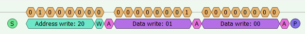
Suppose you needed to set a 8bit register on an I2C device, you may:
- Set the address register.
- Set the DLEN to
2. (the register address and value are a single transaction for writes) - Reset the FIFO (via the control register).
- Push each of the 8-bit data values into the FIFO.
- Reset DONE flag in S (status) register.
- Start the write transfer (via the control register).
- Spin until the DONE flag (in status register) is set.
The read operation is a bit more complicated, but suppose you needed to read from an 8bit register on an I2C device, you may:
- Set the address register.
- Set the DLEN to
1. (the register address and value are two different transactions for reads) - Reset the FIFO (via the control register).
- Push the 8-bit register address into the FIFO.
- Reset DONE flag in S (status) register.
- Start the write transfer (via the control register).
- Spin until the DONE flag (in status register) is set.
- Reset the FIFO (via the control register).
- Push the 8-bit register value into the FIFO.
- Reset DONE flag in S (status) register.
- Start the read transfer (via the control register).
- Spin until the DONE flag (in status register) is set.
- Read the received value from the FIFO.

Once you see the pattern that is happening, you can evolve it to deal with large data sets by setting DLEN to larger values and implementing a thread or loop to continually top off the FIFO until the transfer is complete.
Application
The I2C chip I'm using is a 16bit GPIO expander (MCP23017). The 16bits are split into 2 x 8bit ports that can each be independently configured for input or output. On reset, all of the ports are configured for inputs so we configure one of the ports for output to return the result of any challenges we send it on the first port. The chip address is 0x20.
Without going into how I2C digital signals work, we need to perform 3 operations:
-
Write to register on MCP23017 to configure ports (1 byte for register addr
0x01, 1 byte for register value0x00).i2cset(i2cc, 0x20, 0x01, 0x00); -
Write to register on MCP23017 to configure challenge parameters (1 byte for register addr, 1 byte for register value).
i2cset(i2cc, 0x20, 0x13, p1 << 4 | p2);
-
Write to register on MCP23017 to read port value (1 byte for register addr), then read value returned from MCP23017 port (1 byte for register value).
i2cget(i2cc, 0x20, 0x12);
The Whole Thing in C
Click to see source.
#include <stdio.h>
#include <stdint.h>
#include <stddef.h>
#include <stdlib.h>

#include <sys/mman.h>
#include <sys/types.h>
#include <sys/stat.h>
#include <fcntl.h>

#define GPIO_BASE (0xfe200000)
// Pin configuration
#define GPFSEL0 (0/sizeof(uint32_t))
// Set output value
#define GPSET0 (0x1c/sizeof(uint32_t))
// Clear output
#define GPCLR0 (0x28/sizeof(uint32_t))
// Check level
#define GPLEV0 (0x34/sizeof(uint32_t))
// Pullup/Pulldown configuration
#define GPIO_PUP_PDN_CNTRL_REG0 (0xe4/sizeof(uint32_t))

// Broadcom calls I2C the Broadcom Serial Controller (BSC)
#define BSC1_BASE (0xfe804000)
// Easier to read alias.
#define I2C1_BASE (BSC1_BASE)
// Control register
#define I2C_C (0/sizeof(uint32_t))
// Status register
#define I2C_S (0x04/sizeof(uint32_t))
// Packet Length register
#define I2C_DLEN (0x08/sizeof(uint32_t))
// Address register
#define I2C_A (0x0c/sizeof(uint32_t))
// 8-bit wide data fifo register
#define I2C_FIFO (0x10/sizeof(uint32_t))

#define I2C_MODE_BYTE (1)

volatile uint32_t * mmap_gpio()
{
  int gpioctrlfd = open("/dev/mem", O_RDWR | O_SYNC);

  if (gpioctrlfd == -1) {
    printf("error opening /dev/mem.\n");
    exit(0);
  }

  volatile uint32_t *gpioctrl = (volatile uint32_t *)mmap((void *)GPIO_BASE, 0x100, PROT_READ | PROT_WRITE, MAP_SHARED, gpioctrlfd, GPIO_BASE);
  if (gpioctrl == (void *)-1) {
    printf("Failed to mmap.\n");
    exit(0);
  }

  return gpioctrl;
}

void init_gpio(volatile uint32_t *gpioctrl)
{
  // Clear config for GPIO 2 and 3 (pin 3 and 5)
  gpioctrl[GPFSEL0] &= ~0x00000FC0;
  // Set GPIO 2 and 3 to Alt Func 0: SDA1/SDC1 (pin 3 and 5)
  gpioctrl[GPFSEL0] |= 0x00000900;

  // Clear GPIO 2 and 3 resistor config.
  gpioctrl[GPIO_PUP_PDN_CNTRL_REG0] &= ~0x000000F0;
  // Set GPIO 2 and 3 pullup resistor config.
  gpioctrl[GPIO_PUP_PDN_CNTRL_REG0] |= 0x00000050;

  printf("GPFSEL0 (0x%08x) = 0x%08x\n", &gpioctrl[GPFSEL0], gpioctrl[GPFSEL0]);
  printf("PUP_PDN (0x%08x) = 0x%08x\n", &gpioctrl[GPIO_PUP_PDN_CNTRL_REG0], gpioctrl[GPIO_PUP_PDN_CNTRL_REG0]);
  printf("GPLEV0 (0x%08x) = 0x%08x\n", &gpioctrl[GPLEV0], gpioctrl[GPLEV0]);
}

void i2c_enable(volatile uint32_t *i2cc)
{
  i2cc[I2C_C] = 0x00008000;
}

void reset_fifo(volatile uint32_t *i2cc)
{
  // Clear FIFO
  i2cc[I2C_C] |= 0x00000030;
}

uint32_t fifo_empty(volatile uint32_t *i2cc)
{
  return (i2cc[I2C_S] >> 6) & 0x1;
}

uint32_t xfer_done(volatile uint32_t *i2cc)
{
  return (i2cc[I2C_S] >> 1) & 0x1;
}

uint32_t xfer_active(volatile uint32_t *i2cc)
{
  return i2cc[I2C_S] & 0x1;
}

uint32_t xfer_error(volatile uint32_t *i2cc)
{
  return (i2cc[I2C_S] >> 8) & 0x1;
}

uint32_t fifo_len(volatile uint32_t *i2cc)
{
  return i2cc[I2C_DLEN] & 0xFFFF;
}

void reset_done(volatile uint32_t *i2cc)
{
  i2cc[I2C_S] = 1 << 1;
}

void write_start(volatile uint32_t *i2cc)
{
  i2cc[I2C_C] |= 0x00000080;
}

void read_start(volatile uint32_t *i2cc)
{
  i2cc[I2C_C] |= 0x00000081;
}

void xfer_block(volatile uint32_t *i2cc)
{
  while (xfer_done(i2cc) != 1) {;}
}

void xfer_mode(volatile uint32_t *i2cc, uint8_t mode)
{
  i2cc[I2C_DLEN] = mode;
}

void i2cset(volatile uint32_t *i2cc, uint8_t chip_addr, uint8_t reg_addr, uint8_t value)
{
  i2cc[I2C_A] = (uint32_t)chip_addr;
  xfer_mode(i2cc, 2);

  // Write Register Address
  reset_fifo(i2cc);
  i2cc[I2C_FIFO] = (uint32_t)reg_addr;
  i2cc[I2C_FIFO] = (uint32_t)value;
  reset_done(i2cc);
  write_start(i2cc);
  xfer_block(i2cc);
}

uint32_t i2cget(volatile uint32_t *i2cc, uint8_t chip_addr, uint8_t reg_addr)
{
  i2cc[I2C_A] = (uint32_t)chip_addr;
  xfer_mode(i2cc, I2C_MODE_BYTE);

  // Write Register Address
  reset_fifo(i2cc);
  i2cc[I2C_FIFO] = (uint32_t)reg_addr;
  reset_done(i2cc);
  write_start(i2cc);
  xfer_block(i2cc);

  // Read Register Value
  reset_fifo(i2cc);
  reset_done(i2cc);
  read_start(i2cc);
  xfer_block(i2cc);

  return i2cc[I2C_FIFO] & 0xFF;
}

volatile uint32_t *mmap_i2cc()
{
  int i2ccfd = open("/dev/mem", O_RDWR | O_SYNC);

  if (i2ccfd == -1) {
    printf("error opening /dev/mem for i2c controller.\n");
    exit(0);
  }

  volatile uint32_t *i2cc = (volatile uint32_t *)mmap((void *)I2C1_BASE, 0x20, PROT_READ | PROT_WRITE, MAP_SHARED, i2ccfd, I2C1_BASE);
  if (i2cc == (void *)-1) {
    printf("Failed to mmap for I2C1 controller.\n");
    exit(0);
  }

  return i2cc;
}

uint8_t challenge(volatile uint32_t *i2cc, uint8_t chip_addr, uint8_t p1, uint8_t p2)
{
  //printf("Set the nibbles we want to XOR (`XOR(0xA, 0x3)`) in GPIOB\n");
  i2cset(i2cc, chip_addr, 0x13, p1 << 4 | p2);

  //printf("If everything is good, we'll get `0x09` from GPIOA\n");
  return i2cget(i2cc, chip_addr, 0x12);
}

int main()
{
  volatile uint32_t *gpioctrl = mmap_gpio();
  init_gpio(gpioctrl);

  volatile uint32_t *i2cc = mmap_i2cc();
  i2c_enable(i2cc);

  //printf("Set GPIOB port to all outputs\n");
  i2cset(i2cc, 0x20, 0x01, 0x00);

  uint8_t p1 = 0x5;
  uint8_t p2 = 0xA;
  uint8_t result = challenge(i2cc, 0x20, p1, p2);
  printf("xor(0x%02x, 0x%02x) = 0x%02x (expected 0x%02x)\n", p1, p2, result, p1 ^ p2);
  if (result == (p1 ^ p2)) {
    printf("Passed!\n");
  } else {
    printf("Failed!\n");
  }

  return 0;
}
Notes On The Code
- I started out this article by complaining about actual embedded development. I'll highlight that while I am using Linux, I only depend on
/dev/memand themmap()functionality of Linux. If you replace the calls tommap_gpio()/mmap_i2c()with physical addresses in a bare metal environment, everything should still work.
The Whole Thing in U-Boot Shell
# C 0xfe804000
# S 0xfe804004
# DLEN 0xfe804008
# A 0xfe80400c
# FIFO 0xfe804010

# set gpio config for i2c => 0xfe200000 |= 0x00000900
setexpr v1 *0xfe200000 \| 0x00000900 ; mw.l 0xfe200000 ${v1} 1

# clear gpio resistor config => 0xfe2000e4 &= 0xFFFFFF0F
setexpr v1 *0xfe2000e4 \& 0xFFFFFF0F ; mw.l 0xfe2000e4 ${v1} 1
# set gpio pull ups => 0xfe2000e4 &= 0x00000050
setexpr v1 *0xfe2000e4 \| 0x00000050 ; mw.l 0xfe2000e4 ${v1} 1

# enable i2c => 0xfe804000 = 0x00008000;
mw.l 0xfe804000 0x00008000 1
# Set address => 0xfe80400c = 0x00000020;
mw.l 0xfe80400c 0x00000020 1

# ---> Do writes
# Set DLEN to 2 => 0xfe804008 = 2
mw.l 0xfe804008 0x00000002 1

# reset fifo => 0xfe804000 |= 0x00000030;
setexpr v1 *0xfe804000 \| 0x00000030 ; mw.l 0xfe804000 ${v1} 1
# Set GPIOB to output => 0xfe804010 = 0x01, 0xfe804010 = 0x00
mw.l 0xfe804010 0x00000001 1
mw.l 0xfe804010 0x00000000 1
# reset done => 0xfe804004 = 1 << 1;
mw.l 0xfe804004 0x00000002 1
# write start => 0xfe804000 |= 0x00000080;
setexpr v1 *0xfe804000 \| 0x00000080 ; mw.l 0xfe804000 ${v1} 1

# ---> Check status
#setexpr v1 *0xfe804004 \& 0x00000002 ; print v1

# reset fifo => 0xfe804000 |= 0x00000030;
setexpr v1 *0xfe804000 \| 0x00000030 ; mw.l 0xfe804000 ${v1} 1
# Set challenge params
mw.l 0xfe804010 0x00000013 1
mw.l 0xfe804010 0x000000A3 1
# reset done
mw.l 0xfe804004 0x00000002 1
# write start
setexpr v1 *0xfe804000 \| 0x00000080 ; mw.l 0xfe804000 ${v1} 1
# ---> Check status
#setexpr v1 *0xfe804004 \& 0x00000002 ; print v1

# ---> Do read
# Set DLEN to 1
mw.l 0xfe804008 0x00000001 1
# reset fifo
setexpr v1 *0xfe804000 \| 0x00000030 ; mw.l 0xfe804000 ${v1} 1
mw.l 0xfe804010 0x00000012 1
# reset done
mw.l 0xfe804004 0x00000002 1
# write start
setexpr v1 *0xfe804000 \| 0x00000080 ; mw.l 0xfe804000 ${v1} 1
# ---> Check status
#setexpr v1 *0xfe804004 \& 0x00000002 ; print v1

# reset fifo
setexpr v1 *0xfe804000 \| 0x00000030 ; mw.l 0xfe804000 ${v1} 1
# reset done
mw.l 0xfe804004 0x00000002 1
# read_start
setexpr v1 *0xfe804000 \| 0x00000081 ; mw.l 0xfe804000 ${v1} 1
# ---> Check status
#setexpr v1 *0xfe804004 \& 0x00000002 ; print v1
# ---> Check FIFO
setexpr result *0xfe804010 \& 0x000000FF ; print v1