🔌 Power 🔋
This document is not yet written.
What is voltage?
Before we jump into What is a digital signal?, lets review What is voltage? Conceptually, voltage is a pressure that drives electrons through a circuit. The amount or rate of electrons flowing through the circuit is the current. Current is measured as the amperage or amps and voltage is measured in volts. Often in digital circuits the amperage is measured in milliamps or mA.

There are two primary ways that electrons flow:
-
Alternating Current (AC) - Voltage that alternates in a sine wave over a regular time. This type of voltage is the output of a rotary generator. Its commonly used for delivering current over long distances due to its efficiency. The wall outlet and the power that travels over lines on the top of telephone poles is AC.
-
Direct Current (DC) - Voltage that remains at a constant voltage (within a given threshold.) This can be visualized as a "straight line" (in contrast to a wave). DC voltage is the output of stored energy (e.g. batteries, capacitors) Most smaller electronics or digital electronics run on DC because it provides a more consistent current.
What is resistance?
To sum up resistance succinctly as possible:
- The opposition to current flow in an electrical circuit (i.e. the lasso in the above image.)
- Resistance is measures in Ohms and symbolized by the greek "omega" symbol: Ω
- All materials resist current flow to some degree (i.e. all material contribute to resistance).
Note: You should never measure the resistance of an operating circuit.
Ohms Law
Ohms Law describes the mathematical relationship between current, voltage, and resistance. It is common to determine the resistance of an operating circuit using only voltage and current measurements.
Ohms Law can be expressed as:
Voltage (volts) = Current (amps) * Resistance (ohms)
Current (amps) = Voltage (volts) / Resistance (ohms)
Resistance (ohms) = Voltage (volts) / Current (amps)
You may also see voltage referred to as E or V, current as I or A, and resistance as R or Ω.
Reference Ground
Voltage is also referred to as the potential difference. It is the difference of electrical potential between two points in a circuit (i.e. the difference between the voltage source and its ground). In other words, the voltage that a component is processing is the difference between its input voltage and ground pins.
Printed circuit boards (PCBs) are composed of multiple layers. One of these layers is a ground layer so that components on the board only need to connect a via to this layer to establish a connection with ground.
When measuring voltages of a board, its important to use the same reference ground that the components are using. Electricity will always attempt to find the path of least resistance and if you use an incorrect ground you could risk interconnecting two circuits that were never intended to be connected; at best creating bad measurements and at worst causing irreversible damage to the circuit. For this reason, it is important to locate a quality reference ground when measuring circuits or performing any in-circuit operations.
Note: Locating reference ground was referenced in the Internal Visual Inspection section of this material.
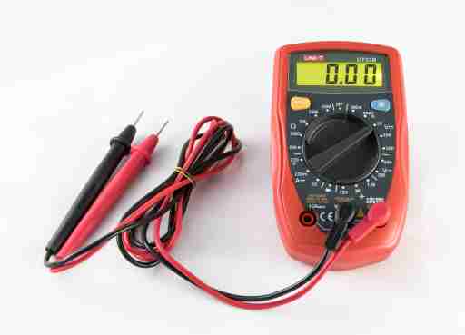
Multimeters
A common tool used with inspection and analysis of circuitry (e.g. voltage levels) is a multimeter.
Multimeters can measure a variety of things:
- AC Voltage - Alternating current moves in waves.
- DC Voltage - Direct current is constant and is used extensively in digital circuits.
- Ohms (i.e. resistance) - You can use measure resistance with this function. It can be handy for checking continuity within a circuit or measuring a resistor when I don't want to look up the ohms from the markings on the components.
- Continuity - Typically makes an audible beep when resistance is zero across the leads. Note: Its often safer to measure resistance manually to determine continuity. This is because you could be connected higher voltages to disconnected circuits and inadvertently overdrive a component. Note: Only measure ohms and continuity on an unplugged board.
The multimeter typically has 3 connections. By convention the black lead is used as the negative or ground. The lead labeled V or with an Ω (omega/ohm symbol) and usually colored red is used for the positive lines for measuring voltages and resistance.
If you want to measure the current of a circuit, the circuit itself must go through the multimeter. This is what the lead labels with A or mA and colored red is used for. Note: There is usually a maximum amperage that the multimeter is safe to operate with labeled on the meter itself.
Caution: Never use the multimeter leads between two different boards. Different boards will have different reference voltages and may cause damage from short circuits.
Caution: Probing a live circuit is very risky. You can very easily cause a short that may damage or degrade the circuit.
Misc Info
Click to read informaiton on dirty power.
Dirty Power
Nearly all digital circuits use DC. Digital products that source AC power usually convert the AC to DC with a power supply that does a good enough job at keeping voltage levels constant. What I mean by good enough is that while digital circuits aim for clean constant voltage levels, they live in an analog world where nothing is perfect. Therefore the voltage levels in a DC circuit usually output a non-zero amount of noise or ripple with them. Cheap wall warts can generate whats known as dirty power. This dirty power is a power source that has a large amount of noise and ripple.
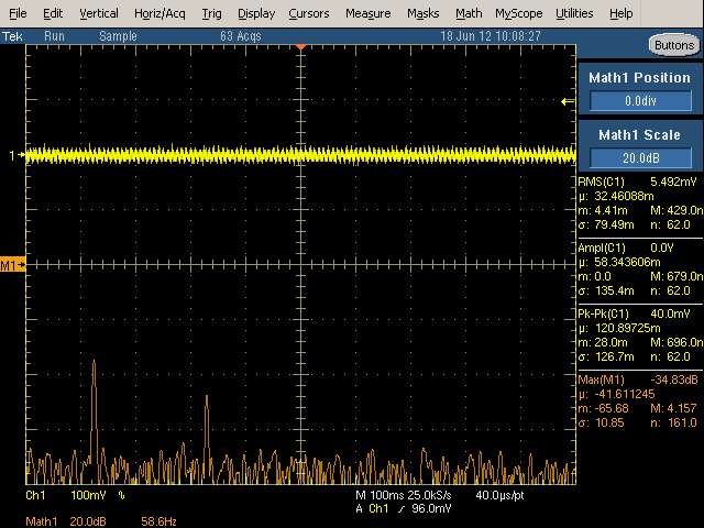
From Ken Shirriff's blog, here are two images of different 5v USB chargers:
-
An authentic Apple iPhone charger:
-
A counterfeit Apple iPhone charger:
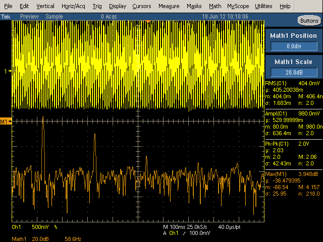
Notice that the first has what we might interpret as clean power and yet it still shows noise on the line. In contrast, the other has very dirty power. While both of these USB chargers exists in identical cases, they are in fact completely different designs and have completely different manufacturing properties. The latter could actually be considered a safety hazard.